From e-vehicles to consumer electronics and implantable medical devices, standards and expectations for the quality and reliability of sealed devices and components continue to rise. This puts the burden on manufacturers to employ methods of leak testing that are objective, reliable and repeatable.
Dunk testing is a popular testing method for sealed components and devices. It’s also time consuming, subjective, prone to operator error and, in those cases involving sensitive electronics, destructive if water does penetrate the item being tested.
Testing with air is a much better alternative that is nondestructive, measurable and quicker to keep pace with production. But sealed components can’t be tested with conventional pressure or vacuum decay testing methods. They lack any ports, valves, or other means of applying pressure or vacuum for testing purposes.
We must test instead by placing the device or part within a sealed chamber. Then, depending on the acceptable leak rate and the usage scenario of the device in question, we have three options:
- Volumetric fill testing with pressure
- Volumetric fill testing with a vacuum
- A tracer gas method
Volumetric fill testing with pressure
This is a common approach that is suitable for sealed parts that must meet the IP67 standard for resistance to penetration. To meet this standard, the part in question must be sufficiently watertight to withstand immersion in one meter of water for 30 minutes.
The test part is placed in a sealed chamber. Because we are testing parts that have a fixed amount of free air space within them, the part must be tested in a leak-tight chamber with minimal volume around the part—we typically aim to match the volume of free air space that is within the part. We do this because the amount of air volume in the chamber does influence the test cycle time and the sensitivity of the leak test. If the chamber has too much relative air space or the part has little to no internal free air space, a leak can easily be masked. So to optimize both cycle time and sensitivity, it is best to use a chamber that is custom formed to the part.
We then test using first a gross leak test and then a fine leak test. Why take this two-step approach?
The challenge is that a sealed part with a gross leak (large hole) will pass a fine leak test when tested without a controlled fill. This occurs because test pressure will fill the chamber and part at the same time. The result is that no pressure change is measured during the actual test. We must first determine if the part has a gross leak before we can carry out the critical fine leak test that will determine pass/fail.
In gross leak testing, air travels into the test chamber via the chamber’s isolation valve, and pressure is equalized between the chamber and the reference volume tank. Gross leak testing provides almost immediate results by verifying that equalized pressure between the two volumes has not fallen below a pre-set pressure. If a sealed device passes the gross leak test, it can then undergo fine leak testing. If it doesn’t, it’s either scrapped or sent to the repair bay.
A fine leak test measures pressure loss in the test chamber over an extended period of time. The test chamber’s isolation valve is closed, and pressure inside the chamber is monitored for gradual loss. Any change in pressure indicates that air from the chamber is infiltrating the object. The fine leak test is identified as a pressure drop over time (x psi loss per x seconds) or as a calibrated volumetric flow rate (scc/m – standard cubic centimeters per minute). A calibrated flow rate leak test serves as a very repeatable low-level leak test for non-water leak rates equivalent to IP67 specifications.
Products that are tested with this method usually include devices that run the risk of failure due to internal electrical short. However, water vapor can also be a reason for failure if the component has a viewable screen that may show internal condensation or fog.
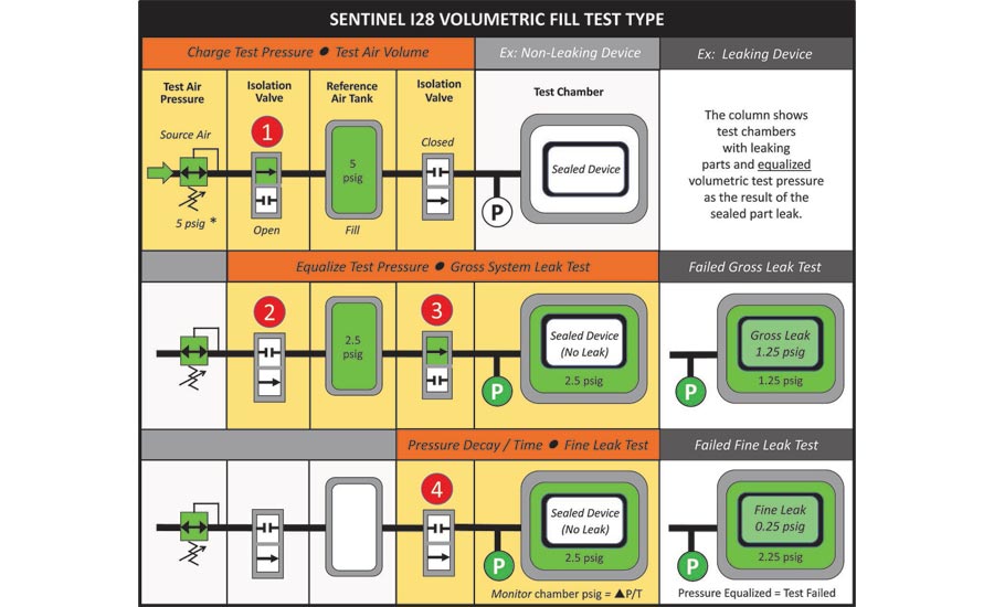
Imagine the volume of your reference air tank being the same of the volume of the free space of the chamber surrounding the outside of the part and neglect all the tubing and inefficiencies. If the reference volume, example 5 psig, is allowed to flow into the test chamber with a good part then the equalized pressure would be around 2.5 psig. If there was a gross leak in the part and the part was the same volume as the reference tank then the new pressure would be 01.25 psig and the test would fail. If the part passes the gross leak test a ‘fine’ pressure decay leak test is performed on the part.
Volumetric fill testing with a vacuum
For a volumetric fill test with a vacuum, we are evacuating air from the test chamber to create a vacuum instead of pressurizing the chamber with air. The same need exists with vacuum versus pressure to conduct a gross leak test prior to a fine leak test. With a vacuum, any pressure change during the fine leak test indicates that air is leaking into the chamber from the test part.
Now, why and when do we use a vacuum instead of pressurized air?
We may opt for a vacuum in those instances where the part in question will undergo atmospheric pressure changes, like electronic components in a vehicle that will be subject to pressure changes associated with changes in elevation. We use a vacuum to simulate those lighter atmospheric pressures experienced when, for example, driving up and through the mountains.
The tracer gas method – time for a helium bomb
Not in any explosive sense, of course. In this case, a key part of the test cycle is to bombard/saturate the test part with helium within a pressure chamber. (Another option is to have manufactured the part in a helium-rich environment so that the assembled part contains within it a certain percentage of helium.)
We use this approach with parts and devices that must meet the most stringent of leak test requirements—any movement of material at the molecular level. We may be testing for either penetration of the device, or loss of a desired gaseous state of equilibrium from within the device through any unwanted leak path. Implantable medical devices are one example of items that are tested with this method.
In this case, the test part is placed in the leak-tight chamber and bombed with helium. If there are leak paths present, the helium will be forced through them and into the part.
The test then proceeds by sniffing with a mass spectrometer for any evidence that helium is leaking from part. In these cases, it’s important to set the right test parameters relative to the part specifications and allow sufficient time for helium to penetrate any leak path and accumulate within the test part.
The right test for the job
Increasingly advanced implantable medical technology, complex in-vehicle electronics systems for navigation and self-driving, and even growing consumer expectations around the durability of the common smartphone demand constant improvements in quality assurance on the production line.
One thing all these scenarios have in common is a need for a better leak test that can tackle the challenge of a sealed device. To maintain production volumes, to reduce scrap and rework, and to contain costs, manufacturers need an option that is reliable, repeatable and objective.
A volumetric approach with air or a tracer gas is the answer. Why get wet if you don’t have to? NDT